
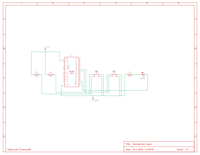
Button
This is a simple program that controls an LED using two buttons.
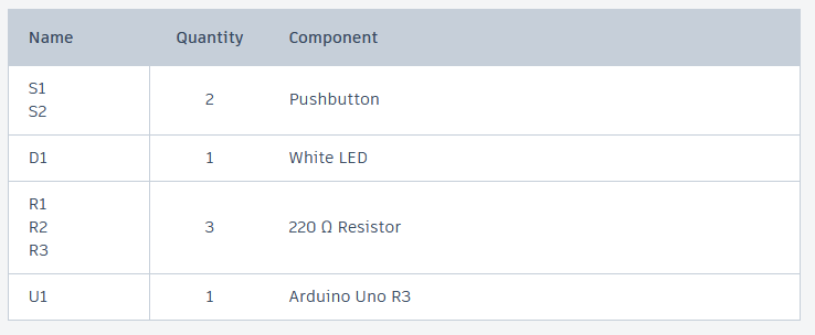
const int button1Pin = 7;
const int button2Pin = 6;
const int ledPin =  13;

void setup()
{
  pinMode(button1Pin, INPUT);
  pinMode(button2Pin, INPUT);
  pinMode(ledPin, OUTPUT);
}

void loop()
{
  int button1State, button2State;

  button1State = digitalRead(button1Pin);
  button2State = digitalRead(button2Pin);

  if (((button1State == LOW) || (button2State == LOW))
      && !
      ((button1State == LOW) && (button2State == LOW)))
  {
    digitalWrite(ledPin, HIGH);
  }
  else
  {
    digitalWrite(ledPin, LOW);
  }
}
- Variable Declaration:
button1Pin = 7;– This line sets up a button connected to pin number 7.button2Pin = 6;– This line sets up another button connected to pin number 6.ledPin = 13;– This line sets up an LED connected to pin number 13.
- Setup Function:
void setup()– This function runs one time when you start the Arduino.- Inside this function:
pinMode(button1Pin, INPUT);– It sets the first button as an input device, meaning it can receive signals (when you press the button).pinMode(button2Pin, INPUT);– It sets the second button just like the first.pinMode(ledPin, OUTPUT);– It sets the LED as an output device, meaning it can show signals (light up).
- Loop Function:
void loop()– This function runs over and over again after the setup is done.- Inside this loop:
button1State = digitalRead(button1Pin);– It checks if the first button is pressed or not.button2State = digitalRead(button2Pin);– It checks if the second button is pressed just like the first.- The
ifstatement checks two things:- If either button 1 or button 2 is pressed (but not both at the same time), then turn the LED on.
- If neither button is pressed, or both buttons are pressed at the same time, then turn the LED off.
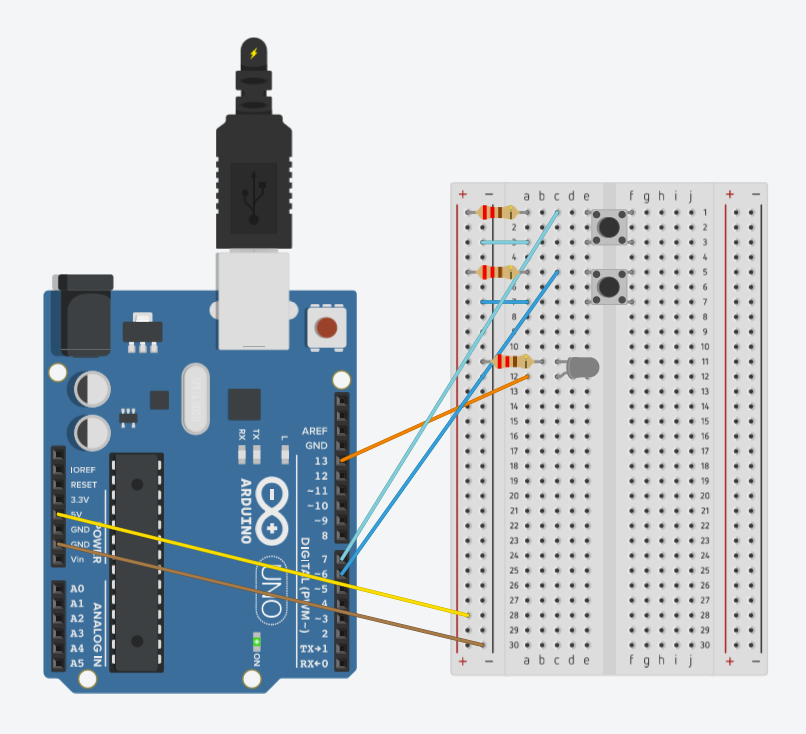
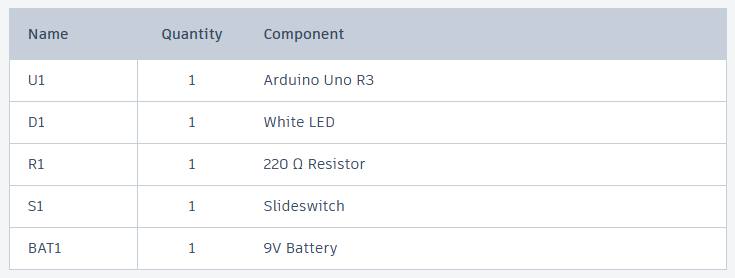
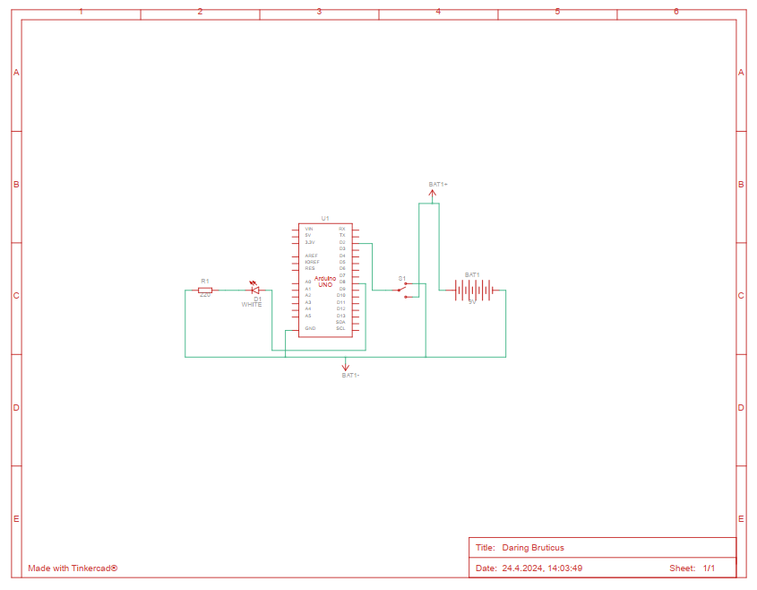
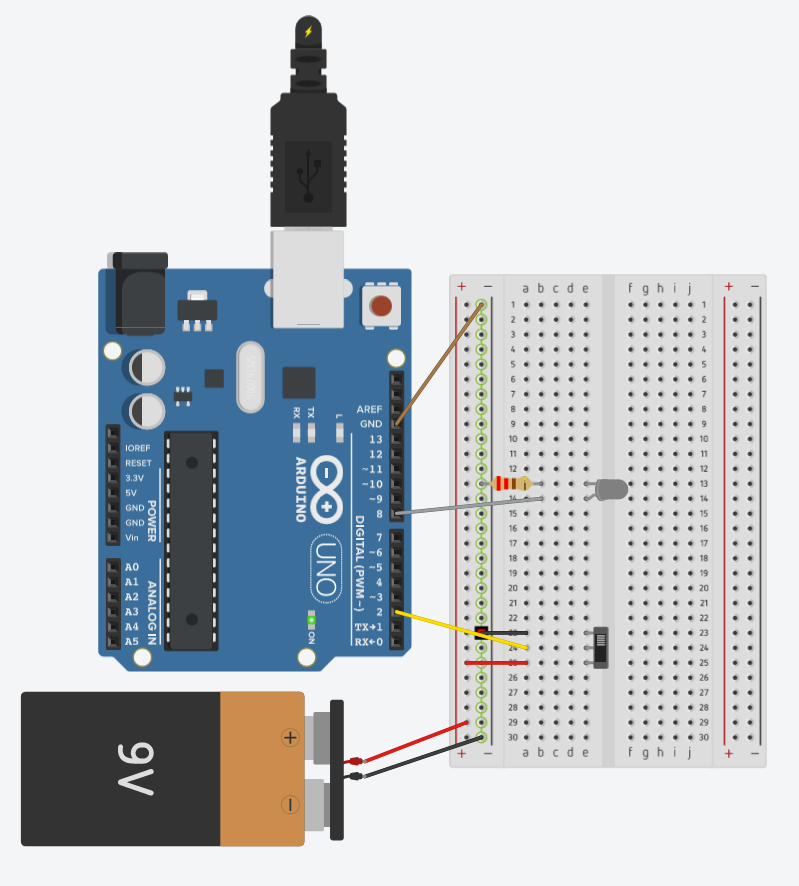
Slideswitch
This program lets a switch control an LED. When you turn the switch ON, the LED lights up. When you turn the switch OFF, the LED goes out.
int swPin = 2;
int ledPin = 8;
int switchstate = 0;

void setup()
{
	pinMode(swPin, INPUT);
  	pinMode(ledPin, OUTPUT);
}

void loop()
{
	switchstate = digitalRead(swPin);
  	if (switchstate == HIGH)
    {
    	digitalWrite(ledPin, HIGH);
    }
  	else
    {
    	digitalWrite(ledPin, LOW);
    }
}
- Variable Declaration:
int swPin = 2;– a pin number for the switch.int ledPin = 8;– a pin number for the LED (a small light)- int switchstate = 0; – This line creates a variable called
switchstateto remember if the switch is ON (HIGH) or OFF (LOW). It starts at 0, which means OFF.
- Setup Function:
pinMode(swPin, INPUT);– This makes pin 2 an input, meaning it expects to receive a signal (like from a switch being turned on or off).pinMode(ledPin, OUTPUT);– This makes pin 8 an output, meaning it can send out a signal (like turning a light on or off).
- Loop Function:
switchstate = digitalRead(swPin);– This line checks if the switch is ON or OFF and saves the result inswitchstate.if (switchstate == HIGH)– This line checks if the switch is ON (HIGH means ON).- If the switch is ON:
digitalWrite(ledPin, HIGH);– Turn the LED ON.
- If the switch is OFF:
digitalWrite(ledPin, LOW);– Turn the LED OFF.
- If the switch is ON:
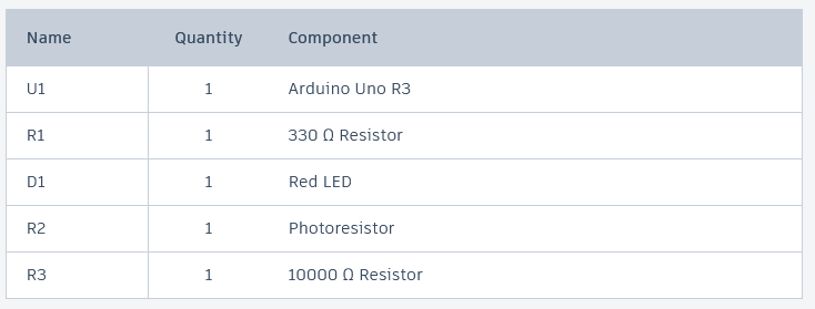
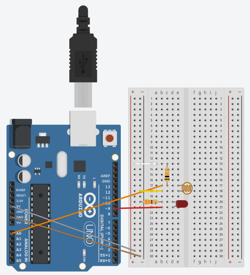
Photoresistor
This code measures light using a sensor and changes the brightness of an LED based on how much light it detects. It also shows the light sensor’s readings on a computer screen. There are two ways in the code to adjust the light levels to control how bright the LED is.
manualTune(): This function is used to normalize the sensor input for predictable conditions where light levels are expected to be within a certain range.
autoTune(): This would be useful for adapting to varying light conditions, automatically adjusting the LED brightness based on the lowest and highest values seen. This method would provide a more adaptive response in environments with changing light conditions.
const int sensorPin = 0;
const int ledPin = 9;
int lightLevel, high = 0, low = 1023;

void setup()
{
  pinMode(ledPin, OUTPUT);
  Serial.begin(9600);
}

void loop()
{
  lightLevel = analogRead(sensorPin);

  manualTune();

  analogWrite(ledPin, lightLevel);

  Serial.print(lightLevel);
  Serial.println("");
  delay(1000);
}

void manualTune()
{
  lightLevel = map(lightLevel, 300, 800, 0, 255);
  lightLevel = constrain(lightLevel, 0, 255);
}

void autoTune()
{
  if (lightLevel < low)
  {
    low = lightLevel;
  }
  if (lightLevel > high)
  {
    high = lightLevel;
  }

  lightLevel = map(lightLevel, low+10, high-30, 0, 255);
  lightLevel = constrain(lightLevel, 0, 255);
}
- Variable Declaration:
const int sensorPin = 0;– The light sensor is connected to analog pin 0 of the Arduino.const int ledPin = 9;– An LED is connected to digital pin 9, for controlling brightness.int lightLevel, high = 0, low = 1023;–lightLevelstores the current light sensor reading.highandloware used in the auto-tune function to store the maximum and minimum sensor values detected.
- Setup Function:
pinMode(ledPin, OUTPUT);– Sets the LED pin as an output.Serial.begin(9600);– Starts serial communication at 9600 baud to send data to the computer.
- Loop Function:
lightLevel = analogRead(sensorPin);– Reads the light level from the sensor.manualTune();– Calls themanualTune()function to adjustlightLevelbased on predefined bounds.analogWrite(ledPin, lightLevel);– Controls the brightness of the LED based on the tunedlightLevel.Serial.print(lightLevel);andSerial.println("");– Prints thelightLevelto the serial monitor.delay(1000);– Pauses the loop for 1000 milliseconds (1 second), controlling the rate at which data is read and reported.
manualTune()Function:- Adjusts
lightLevelto the 0-255 range suitable for PWM control:lightLevel = map(lightLevel, 300, 800, 0, 255);– Remaps thelightLevelfrom the range 300-800 to 0-255.lightLevel = constrain(lightLevel, 0, 255);– Ensures thelightLevelstays within the 0-255 range.
- Adjusts
autoTune()Function:- Adjusts the mapping based on dynamically detected high and low sensor values:
- Updates
lowandhighif the currentlightLevelis outside of previously recorded values. - Remaps
lightLevelbased on these adjusted bounds to provide a more responsive LED brightness control based on actual light conditions. - Uses
constrain()similarly to ensure the output stays within 0-255.
- Updates
- Adjusts the mapping based on dynamically detected high and low sensor values:
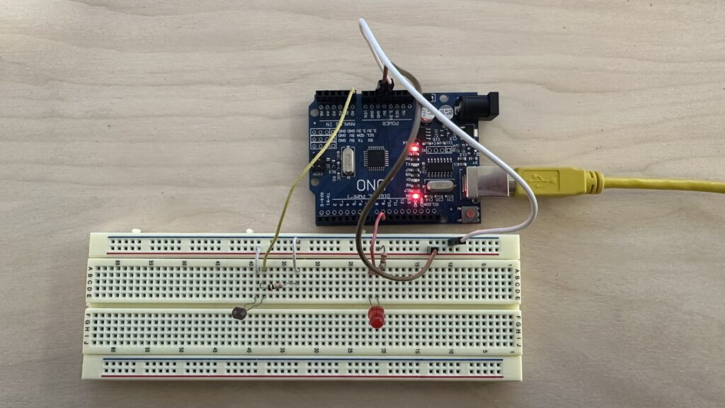
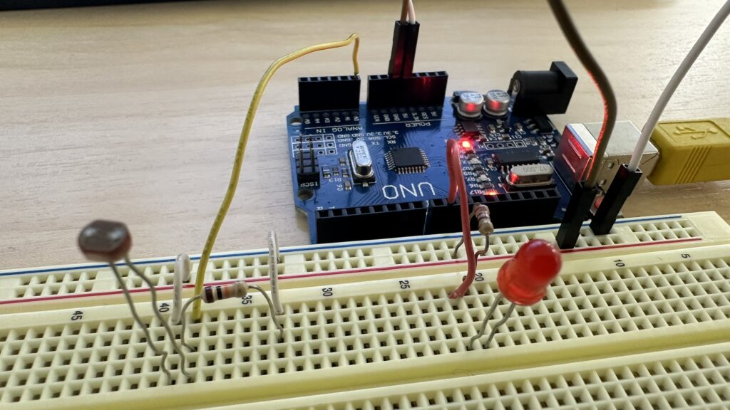
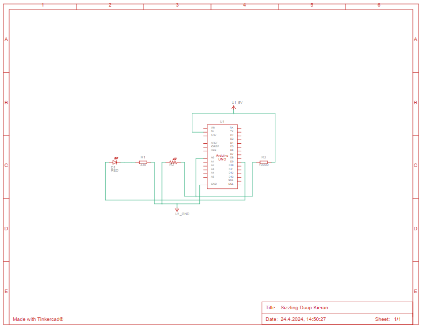
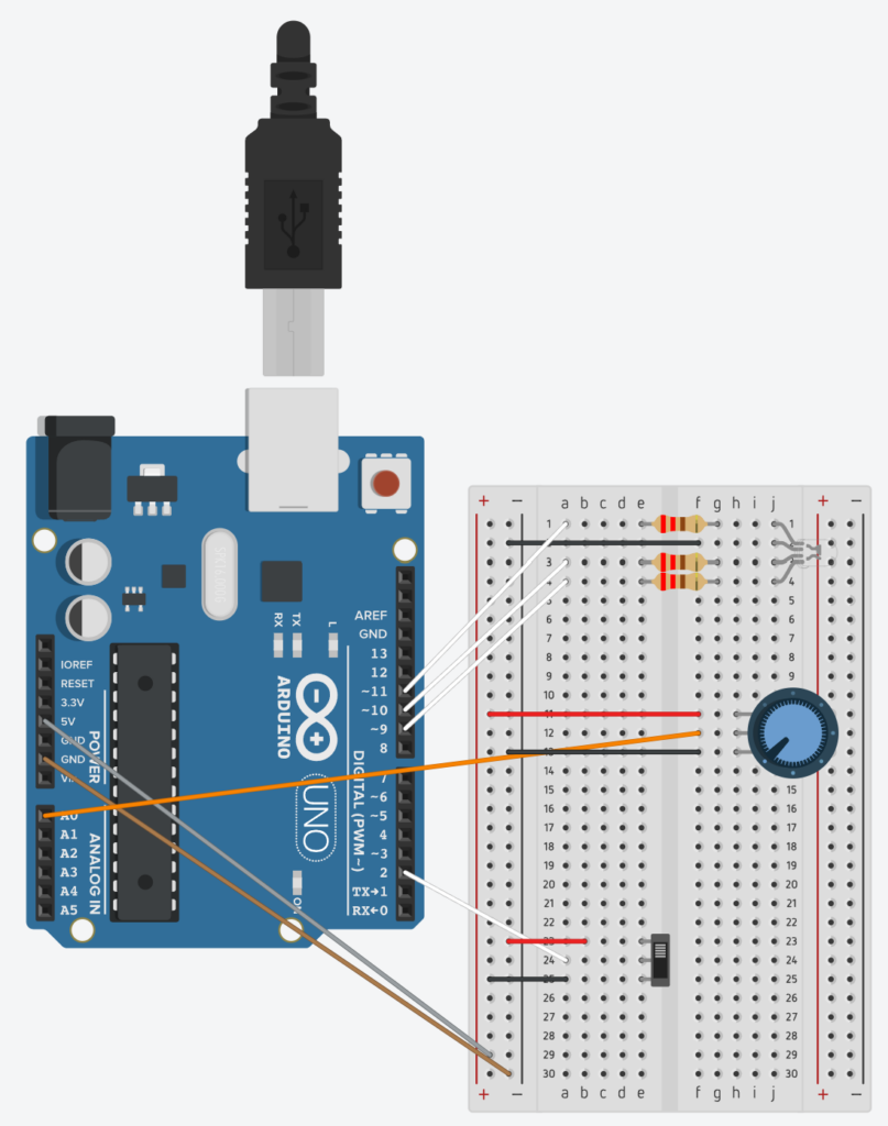
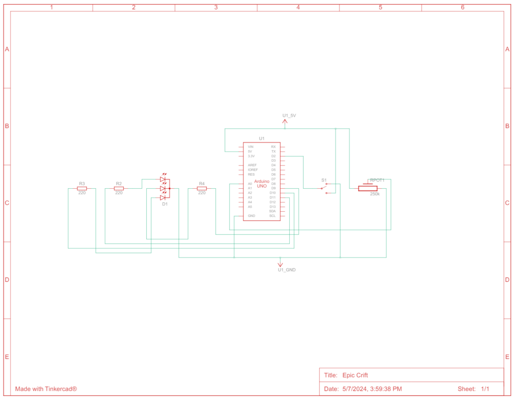
Night light
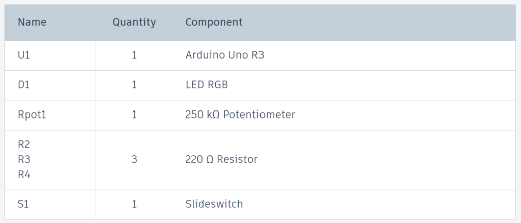
This code is a night light that uses RGB LEDs to display different colors. The night light has multiple modes that can be cycled through by adjusting a potentiometer. It also includes a switch to turn the LEDs on or off.
const int RED_PIN = 11;
const int GREEN_PIN = 9;
const int BLUE_PIN = 10;
const int switch_PIN = 2;

bool ledState = false;
bool lastButtonState = HIGH;

int mode = 1;

void setup() {
  pinMode(switch_PIN, INPUT_PULLUP);
  pinMode(RED_PIN, OUTPUT);
  pinMode(GREEN_PIN, OUTPUT);
  pinMode(BLUE_PIN, OUTPUT);
}

void loop() {
  static unsigned long lastCheck = 0;
  if (millis() - lastCheck > 100) {
    bool switchState = digitalRead(switch_PIN);
    if (switchState != lastButtonState) {
      ledState = !ledState;
      lastButtonState = switchState;
    }
    lastCheck = millis();
  }

  if (!ledState) {
    setColor(0, 0, 0); // Turn off LED
    // Skip executing any modes if LED is turned off
    return;
  }

  int potValue = analogRead(A0);
  mode = map(potValue, 0, 1023, 1, 4);
  switch (mode) {
    case 1:
      modeOne();
      break;
    case 2:
      modeTwo();
      break;
    case 3:
      modeThree();
      break;
    case 4:
      modeFour();
      break;
  }
}

void setColor(int red, int green, int blue) {
  analogWrite(RED_PIN, red);
  analogWrite(GREEN_PIN, green);
  analogWrite(BLUE_PIN, blue);
}

void modeOne() {
  static unsigned long lastUpdateTime = 0;
  static int r = 255, g = 0, b = 0; // Start with Red
  static int state = 0;

  if (millis() - lastUpdateTime > 10) {
    switch (state) {
      case 0: // Red to Yellow (increase green)
      g++;
      if (g >= 255) state++;
      break;
      case 1: // Yellow to Green (decrease red)
      r--;
      if (r <= 0) state++;
      break;
      case 2: // Green to Cyan (increase blue)
      b++;
      if (b >= 255) state++;
      break;
      case 3: // Cyan to Blue (decrease green)
      g--;
      if (g <= 0) state++;
      break;
      case 4: // Blue to Magenta (increase red)
      r++;
      if (r >= 255) state++;
      break;
      case 5: // Magenta to Red (decrease blue)
      b--;
      if (b <= 0) state = 0; // Wrap around to start of cycle
      break;
    }
    setColor(r, g, b);
    lastUpdateTime = millis();
  }
}

void modeTwo() {
  setColor(255, 255, 255); // White
}

void modeThree() {
  setColor(200, 200, 0);  // Yellow
  delay(700);
  setColor(173, 216, 230); // Light Blue
  delay(700);
  setColor(255, 105, 180); // Pink
  delay(700);
  setColor(255, 255, 255); // White
  delay(700);
}

void modeFour() {
  // Gradually change colors with a delay of 1000 ms between updates
  setColor(255, 0, 0);  // Start with Red
  delay(1000);
  setColor(255, 255, 0); // Yellow
  delay(1000);
  setColor(0, 255, 0);  // Green
  delay(1000);
  setColor(0, 255, 255); // Cyan
  delay(1000);
  setColor(0, 0, 255);  // Blue
  delay(1000);
  setColor(255, 0, 255); // Magenta
  delay(1000);
  setColor(255, 0, 0);  // Back to Red
}
- Variable Declaration:
- PINs: are for each color component of the RGB LED (red, green, blue) and a switch for turning the LED on or off.
- Variables:
ledState– Indicates whether the LED is on or off.lastButtonState– Stores the previous state of the switch to detect changes.mode– Determines which color mode is currently active.
- Setup Function:
- Initializes the switch pin as an input with an internal pull-up resistor and sets the RGB pins as outputs.
- The
INPUT_PULLUPpart means the Arduino will automatically use a built-in feature to prevent false readings when nothing is connected. It helps make sure the pin reads as HIGH (like the button is not pressed) unless it is actually connected to the ground through a press.
- Loop Function:
- Timing and Checking the Button State:
- The Arduino keeps track of time with
millis(), which tells you how many milliseconds have passed since the Arduino was last turned on. lastCheckis used to remember when the last button check happened.- If more than 100 milliseconds have passed since the last check, the Arduino reads the state of the button (
switch_PIN) again to see if it has been pressed or released. - If the button’s current state (
switchState) is different from the last state it remembers (lastButtonState), it changes theledState. This means if the LED was on, it turns off, and if it was off, it turns on. - After checking, it updates
lastCheckto the current time.
- The Arduino keeps track of time with
- Turning Off the LED:
- If
ledStateis false (meaning the LED should be off), the functionsetColor(0, 0, 0)is called, which sets the LED colors to black (off). - Then, it uses
return;to skip the rest of the loop. This means if the LED is off, nothing else happens until the next cycle of the loop.
- If
- Reading the Potentiometer and Choosing a Mode:
- The value from a potentiometer connected to
A0is read byanalogRead(A0). This value can be anywhere from 0 to 1023 depending on how much it is turned. - This value is then converted into a mode number (from 1 to 4) using the
map()function, which scales the potentiometer range to these four values. - Based on what mode number is chosen, one of four functions (
modeOne(),modeTwo(),modeThree(),modeFour()) is called. Each function likely controls the LED in a different way, like changing colors or patterns.
- The value from a potentiometer connected to
- Timing and Checking the Button State:
setColor()function:- This function is essential for creating different colors by mixing red, green, and blue light in varying intensities. By changing the parameters
red,green, andblue. - For example, setting
red = 255, green = 255, blue = 0will produce yellow light, whilered = 0, green = 255, blue = 255will give you cyan.
- This function is essential for creating different colors by mixing red, green, and blue light in varying intensities. By changing the parameters
modeOne()function:- Static Variables
static unsigned longlastUpdateTime– Keeps track of when the LED was last updated. It’s used to control the update frequency.r,g,b– Hold the current intensity values for the red, green, and blue components of the LED.state– Tracks which part of the color transition cycle the function is currently processing.
- Timing Control
- The function checks if 10 milliseconds have passed since the last update using
millis()– If less than 10 milliseconds have passed, the function does nothing and returns quickly, effectively throttling the rate of color changes to prevent flickering and allow other code to run. - Color Transition Logic
- The function checks if 10 milliseconds have passed since the last update using
- Switch Statement – Controls the transition between colors using several states (0 through 5). Each case in the switch corresponds to a specific transition between colors:
- Case 0: Increases the green component to transition from pure red to yellow.
- Case 1: Decreases the red component, shifting from yellow to green.
- Case 2: Increases the blue component, changing from green to cyan.
- Case 3: Decreases the green component, transitioning from cyan to blue.
- Case 4: Increases the red component to move from blue to magenta.
- Case 5: Decreases the blue component to return to red.
- Increment/Decrement Logic
- In each state the function modifies one of the RGB values either by incrementing or decrementing it. When the target value for that transition phase is reached (either 0 or 255), the function increments the
statevariable to move to the next phase of the cycle. - When the final transition phase (case 5) completes, it resets
stateto 0, starting the cycle over.
- In each state the function modifies one of the RGB values either by incrementing or decrementing it. When the target value for that transition phase is reached (either 0 or 255), the function increments the
- Color Update
setColor(r, g, b)– Updates the LED with the new color values. This function is called only if the current time interval (every 10 ms) has elapsed since the last update, ensuring a smooth transition.lastUpdateTimeis then updated to the current time, resetting the timer for the next cycle.
- Static Variables